Showing posts with label radio control. Show all posts

Monday, January 06, 2014

Leonardo Torres y Quevedo Telekino


I have written before about the history of radio control and strongly invoked the hallowed name of Nikola Tesla. In 1898, Nicola Tesla staged the first demonstration of radio control. His invention (patent No. 613,809), took the form of a radio-controlled boat, a heavy, low-lying, steel craft about four feet long. At that time radio itself had not been officially patented yet! Tesla's own radio patent wasn't granted until March 1900!

But Tesla didn't do much more with the technology. He licensed his patent and moved on to his other projects. The next inventor to take up the cause was Leonardo Torres y Quevedo Torres. Three years after Tesla won is patent, Torres presented the Telekino at the Paris Academy of Science. In 1903 he did an experimental demonstration of his Telekino... a radio controlled robot  He went on to patent his robot in France, Spain, Great Britain, and the United States.

Torres Quevedo has been working on the idea since about 1901. The term "Telekino" comes from from two Greek words "tele" meaning 'at a distance' and "kine" meaning movement. So it means "movement at a distance" which is of course the whole idea of radio control. His Telekino turned the wheel of a tricycle forward and back and steered. By 1905 Quevedo was applying his ideas to remote control boats as Tesla had demonstrated 7 years earlier.

In 1905 Torres Quevedo organized a public demonstration of a radio controlled boat at a lake in Madrid. If that reminds you of Tesla, that's because it's what he had in mind. Tesla's boat mostly controlled the rudder. Quevedo had server control of the motor as well. He later did another more organized event at the port city of Bilbao was a success in some regards but tit didn't win him the government contracts he wanted. There would be no radio controlled torpedoes or war ships. He moved on to new projects and our dystopian future of drone warfare was delayed slightly.

Wednesday, August 07, 2013

Azon Bomb

The AZON bomb was perhaps the world's first smart bomb.  AZON stood for Azimuth Only, which I'll explain. It was officially named the VB-1, the VB stood for Vertical Bomb. The whole idea of a smart bomb is that primitive explosives aren't very clever. You drop them you throw them... they detonate wherever they land when the impact, fuse or timer triggers the explosion. At some point some military minds began thinking about steering them. This is the fundamental idea behind a "smart" bomb. The  first steering mechanism of course was radio control. This was used mostly in 1944 and 1945. More here.

On this topic, I must give the hat tip to Tesla for inventing radio control in 1898. All later designs are derived from his ideas. This particular design was developed by by Major Henry J. Rand and Thomas J. O'Donnell. the word "design" there sounds like they designed a whole bomb, not so. The Azon Bomb was just a special tail fin unitbolted to a 1,000-pound GP bomb (General Purpose). While that's true, it understates what a big step this was.

With the addition of this unit, the bomb’s trajectory could be adjusted in flight via radio signals which moved the fins. But this didn't allow total control through three dimensional space. It only adjusted the yaw axis. So let's explain that. An airplane manners in 3 axis, yaw, pitch and roll. Roll is controlled by the flaps on the wings and literally could roll the airplane like a barrel. So imagine that rotation as one axis. Pitch is effectively up and down. The pilot pushes the stick forward, you dive, he pulls back you climb. It's controlled by the horizontal flaps (ailerons) on the tail. Yaw is the one you're trying to figure out. Yaw is only left/right movement controlled by the single vertical flap on the tail fin.  Here the Axon bomb is falling (a purely vertical movement) and the axon unit steers with fin adjustments. To aid steering a candela  flare was attached to the tail so a bombardier could see the bomb better for remote steering.

Four antennas wrapped around the fins and signal was tuned by a single on board radio. This was powered by a small battery with about 3 minutes of life. But three minutes was plenty. The transmitter ont eh aircraft operated at 25 watts and controlled 3 signals.  The first signal at 30-40 hertz, triggered the flare. Then two other signals controlled the flaps: one at 475 hertz for left deflection, one on 3,000 hertz for right deflection. these are extremely low frequencies.

Prior to this given good weather hitting large targets like factories was doable, but small targets like railroads, roads and bridges was difficult. But the axon could be steered onto much smaller targets.

Monday, May 20, 2013

Radio Proximity Fuses

In the late 1930s the proximity fuse was developed in the UK.  The Germans were also working in the same arena and had developed some models but the Brits beat them to it. They had been working on a variety of developments to increase what the military called "air defense efficiency."

Into this technological melee they dropped William Alan Stewart Butement. In 1931 he and P. E. Pollard, invented a shipboard radio device for the detection of ships. Today we call it radar. It operated at 600 MHz and using pulse modulation was able to detect ships100 yards away. The Navy wasn't big on it, but others saw potential. By 1938 Butement had ramped up his invention into large scale devices that could be used from land to protect the coast.

In 1939 Butement attempted to improve anti-aircraft guns. It's hard to hit a moving target. He had a better idea.  His plan was a very compact  Radio Direction Finder (RDF) unit placed on the projectile. It would then trigger the detonation when near the target. This was not simple. The RDF had to be small and also durabel enough to be fired out of a cannon. This circuit included glass vacuum tubes. Somehow just over a year the United States was manufacturing projectiles with a proximity fuse. This was also called a VT (variable-time) fuse.


This was not an induction trigger. It wasn't sensing a ferrous body. It was detecting the reflection of radio signals. A later improvement was The transmitter which used the shell body as an antenna and sent out a continuous wave at around 200 MHz. As the shell approaches a reflecting object, (a ship, a plane, the ground) the reflected signal created interference. That pattern changes with proximity. As the objects get closers the signal moves in and out of resonance as the reflected signal length changes; half a wave is resonant, so is a quarter, an eighth etc.

This causes a small oscillation of the radiated power and consequently the oscillator supply current of about 200–800 Hz, the Doppler frequency. This signal is sent through a band pass filter, amplified, and triggers the detonation when it exceeds a given amplitude. Later in life, Butement said that he considered the proximity fuse as his most significant accomplishment.

Wednesday, February 13, 2013

Marilyn Monroe's Drones

Increasingly often I see the press giving coverage to drone warfare. It's good. The issue is morally ambiguous and worthy of public debate. But the use of drones aka radio controlled pilot-less aircraft is nothing new. Nikola Tesla patented radio controlled vehicles in 1898 with a small boat. In a 1915 dissertation on the concept of unmanned flight, Nikola Tesla described an armed, pilot-less aircraft capable of defending the USA. That makes this idea almost a century old.
But the first real-world military use of drones was in 1935. Reginald Denny, Hollywood actor and former WWI British gunner in the Royal Flying Corps. He opened a model plane shop at 5751 Hollywood Blvd in 1934 known as Reginald Denny Hobby Shops. Denny bought a plane design from Walter H. Righter in 1938. They were marketed as the "Dennyplane," with an engine called the "Dennymite".

Righter was only 33 but already a veteran engineer who had worked at the Kinner Airplane & Motor Corp, Hughes Aircraft, and Lockheed. Righter actually manufactured thousands of these for Denny in his own garage. Sales were consistent enough for Righter to move out of the garage and open a 12-man shop at 626 San Fernando Road in Glendale. More here.

Denny thought that cheap RC planes would make for great target practice for training anti-aircraft gunners. It was something he knew a bit about from WWI. In 1935 he demonstrated a prototype target drone for the US army. In 1940, Reginald Denny Hobby Shops won a US Army contract for their radio-controlled target drone, the OQ-2 Radioplane. The Army placed an order for 53 model RP-4s, which the military designated the OQ-1. In1941 US Army placed an even bigger order for RP-5s, which became the US Army OQ-2. Denny manufactured nearly fifteen thousand drones for the US Army during World War II.

The US Navy also bought into the target drone idea. They signed an order for thousands as well and designated it the TDD-1. A factory was opened in the old Timm aircraft plant at the Van Nuys Airport near  Los Angeles for production. Because it was the height of WWII most of the workers were women. It was there in 1944 an Army photographer photographed Norma Jeane Dougherty at work. Those pictures led to a screen test, and to the fame of a woman later known as Marilyn Monroe.

Monday, August 06, 2012

Zoe, Radio Dog

Even a dog can be famous for five minutes. Zoe got written up in at least three geek magazines. She was in both Popular Science and Mechanix Illustrated Magazine in 1939, and Radio Craft in 1940. Zoe was a trained German Shepard, called an Alsatian in the UK. I wouldn't have mentioned that except that Zoe was an Australian Alsatian, and American readers would be confused by the English convention. I was. So more here, here and here.
"ZOE, an Alsatian police dog attached to the Sydney (Australia) Police Force, is shown performing tricks in response to commands issued to her via short-wave radio. A miniature radio receiver was strapped to the animal’s back and a police officer whispered instructions into the microphone of a transmitter located some distance away. Hearing her master’s voice, Zoe dutifully carried out the commands."
The dog is not radio controlled in the technical sense. The dog was trained for 2 years by Constable Denholm with verbal commands like any other trained dog. It's just that in this case the commands are issued by a short wave radio strapped to the dog. Zoe probably recognizes Constable Denholm's voice, but verbal commands. In another demonstation Zoe climbed up and down ladders, turned a faucet on and off, took off her collar, and fired a revolver. For the record there was not a gun strapped to the dog.

For these demonstrations Denholm, strapped a miniature shortwave radio receiver and a battery pack on the back of Zoe. Then from a shack fifty yards away he issued commands into a microphone connected to a portable shortwave transmitter. The fame lasted perhaps two years, what happened to Zoe after that I have no idea.

Wednesday, July 06, 2011

The Radio Control of "Little Boy"

Most people assume that bombs work in real life like they do in Looney Tunes cartoons—they fall out of a plane and they explode upon impact. Those are ballistic bombs.  That is not how all bombs work.  Many operate by radio control. I am not referring to missiles that are steered by radio control. Many times of bombs used by the U.S. military detonate depending on their distance to the ground and that is determined by radio. More here.
On Monday, August 6th, 1945, at 8:15 AM, the Atomic Bomb "Little Boy" was dropped on Hiroshima by an American B-29 bomber, the Enola Gay.  The code names of the first two nuclear bombs were "Fat Man" and "Little Boy."  I only read recently that they were radio controlled. the book E=MC² by David Bodanis detailed the whole arming mechanism. I quote it here at length:
"...Weak radio signals were being pumped down from the bomb to the Shina Hospital directly below. Some of the radio signals were absorbed in the hospitals walls, but most were bounced back skyward. Sticking out of the bomb's back, near the spinning fins, were a number of whiplike thin radio antennae. Those collected the returning radio signals, and used the time lag each took to return as a way of measuring the height remaining to the ground. At 19,000 feet the last rebounded radio signal arrived."
He doesn't mention it above, but another plane flying in formation with the Enola Gay dropped measuring instruments by parachute. I found aversion of the story in the New Yorker that incorrectly describes this device like a timer. "...wires on top of the device were attached to a solenoid unit on the roof of the bomb bay. When the bomb dropped out, the wires came loose from switches inside the clock-box—the brain that told the bomb to drop for forty-five seconds before detonating."  It's correct that a solenoid switch started the sequence, but the count down clock was a back up system. More here.

The radio described by Bodanis was the AN/APS-13 radar unit.  While I can't find a source on the frequencies used by the equipment in this case I do know that a standard AN/APS-13 operates at 410 - 420 MHz with a receiver IF of 30 MHz. The British called these "Archies." One source I read claimed that it detonation was triggered only when two AN/APS-13 radar units identified the critical altitude. They were trying to prevent premature detonation. With the score of the number of other back up systems that seems totally plausible. Some sources claim there were as many as four. More here. They were used as tail radar in allied planes in WWII. This is the device that actually triggered the altimeter fuse. The Duxford Radio Society has pictures of a restored unit here. The device is automated and self contained.

Some of this is still classified today, and I suspect this was not an off-the-shelf AN/APS-13. That device wasn't designed to measure distance. It was a tail warning device, i.e. it warned a pilot that an aircraft was approaching him from the rear. It's effective range was given as 2,000 to 2,500 feet transmitting and receiving a fan-shaped beam behind the airplane. More here. You know the rest of the story but let me quote this from the Yale Avalon Project, and recommend that you visit their website.
"At 8:16 A.M., the Tokyo control operator of the Japanese Broadcasting Corporation noticed that the Hiroshima station had gone off the air. He tried to use another telephone line to reestablish his program, but it too had failed. About twenty minutes later the Tokyo railroad telegraph center realized that the main line telegraph had stopped working just north of Hiroshima. From some small railway stops within ten miles of the city there came unofficial and confused reports of a terrible explosion in Hiroshima. All these reports were transmitted to the Headquarters of the Japanese General Staff."

Wednesday, March 31, 2010

Radio Guides the Plow

In 1932 Popular science ran an article foretelling the use of radio to control plows. The images were rudimentary with long wire aerials slung high over the chassis the full length of the vehicle. Maybe it wasn't elegant, but it was the beginning of an idea. It described the experiment this way:
"Recently, J. J. Lynch, of Miles City, Mont., demonstrated his radio-controlled tractor before 200 electrical experts and business men. Steered from a closed car traveling behind, it plowed around a thirty-acre field. Radio relays beneath the empty driver’s seat operated it in response to a radio transmitter in the control car."
In 1929 the Japanese were looking at radio control. A Japanese army major named Nagayama rebuilt some Fordson tractors for experimental remote control by radio waves. These weren't meant for farming. This was a tank. It was intended for mine clearing and mine laying. It was able to move up to 5 mph.

I found another reference in to the 1934 World's fair in Chicago where a "robot plow" was exhibited which could be started and steered remotely. The International Harvester Company held daily demonstrations of the driverless, radio-controlled McCormick-Deering tractor in a field outside the the Agriculture building. When I read it I assumed the closest thing we had to remote controlled tractors was the little John Deere RC cars. I was way off.As recently as 2004 The International Journal of Vehicle Design publishes an article on the refurbishing of a Ford model 4600 agricultural tractor for remote control operation. The abstract for the article detailed the following:
"Modifications to the tractor involved installing a protective framework, electrical actuators for fuel, brake, clutch, and steering controls, and a radio link for remote operation. The tractor has been used to complete over 30 total side and back upset tests, with no failures of the remote control system."
So the idea is still simmering. But the idea has probably run it's full life-span. It began as science-fiction, and has now become science kitsch. Large-scale agribusinesses have moved past radio-control to GPS controlled plowing with a number of competing systems all in use presently including the IntegriNautics AutoFarm GPS 5001 AutoSteer System. Doesn't that sound like something from the Jetsons?

Thursday, January 05, 2006

The Radio Controller

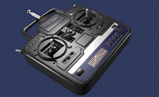
I just read this very detailed piece on Radio Control. It's kind of an overview of radio control theory, entitled "What Happens When I Wiggle the Sticks." The author, Neil McGrath, is a British radio-frequency electrical engineer whose hobby is radio controlled power boats.

The title was quite the grabber. What does happen when I wiggle the sticks? Below I quote:

1. The transmitter broadcasts a radio signal via the antenna containing the positional information set by the controls.
2. The receiver picks up the radio signal via its antenna and decodes the positional information.
3. The receiver distributes the information to the electronic speed control and the rudder servo
4. The electronic speed control switches the main battery power on and off at high speed to regulate the power output of the motor to the level set by the associated transmitter stick.
5. The servo arm will move to the position set by the transmitter stick.
6. Power for the motor comes from the main battery pack.
7. The power for the receiver comes from an independent battery eliminator circuit. The BEC will provides voltage to the receiver from the main battery pack.
8. The power supply for the servo and the control circuitry in the speed controller come from the receiver

All radio control systems generate a radio carrier wave, at a frequency that is determined by the crystal used in the transmitter. These are thankfully not licensed individually. The FCC handles these devices in bulk by allotting a certain set of frequencies and parameters to the devices. The carrier wave is modulated to carry the digital information set by the transmitter controls. There are two methods of modulation used by R/C systems, AM and FM. As a third variable some use a PCM radio to transmit digital data on the FM carrier wave. This is conceptually not that different from IBOC.

In 1898, Nicola Tesla staged the first demonstration of radio control. His invention (patent No. 613,809), took the form of a radio-controlled boat, a heavy, low-lying, steel craft about four feet long. At that time radio itself had not been officially patented yet! Tesla's own radio patent wasn't granted until March 1900! Initially examiners from the US Patent Office were reluctant to recognize improbable claims made in the application "Method of and Apparatus for Controlling Mechanism of Moving Vessels or Vehicles." Confronted with a working model, however, examiners had to issue approval. ...And today we use it to drop missiles on people. Oh, How far we have come.